
Guide to the Use and Maintenance of KUKA Accessory Communication Cables
1. User Guide
Hardware connection
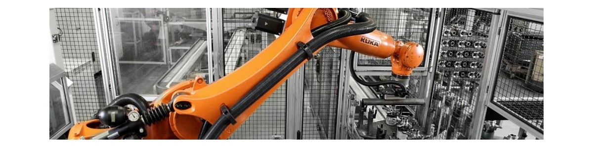
Internal system connections: The cable connections within the KUKA robot system mainly consist of those between the robot body and the controller, the teaching device and the controller, and the power supply and the controller.
Robot body and controller: It is necessary to connect the motor power line and the encoder data line. The main body side of the robot has been connected at the factory. On the controller side, two motor power lines need to be connected, which are then linked to the motor power lines on the main body side through adapters.
Teaching device and controller: The cable of the teaching device is a gray wire. One end is connected to the teaching device, and the other end interface is inserted into the XG19 port of the controller. After insertion, you need to push the plug upwards to make the upper black part automatically rotate about 25°, and the plug will automatically lock in place.
Power supply and controller: Insert the power cord into the XD1 interface of the panel, and connect the other end to a 220V/50Hz power supply. The power cord interface adopts the European standard plug by default. If a national standard plug needs to be inserted, a European standard adapter plug should be used.
System peripheral connection: Mainly refers to the connection between the robot body and the end effector, which is used to realize the specific operation functions of the robot.
Input/output signal interfaces: Interface X76 at the base, interface X96 at the wrist of the four axes. Eight wires are reserved for the two interfaces, and the pins correspond one by one.
Air source interface: At the four-axis wrist, the robot body reserves four air source interfaces, namely AIR1 to AIR4, with a maximum pressure resistance of 0.7MPa and an outer diameter of the air pipe of 4mm.
Communication protocol configuration
PROFIBUS DP communication configuration:
Hardware connection: Confirm that the KUKA robot controller has the PROFIBUS DP interface, configure the EL6731-0010 PROFIBUS DP Slave module, and connect this module to the X44 interface of the KUKA KR C4 controller. Use the PROFIBUS DP cable that complies with industrial standards. One end is connected to the EL6731-0010 PROFIBUS DP Slave module of the KUKA robot, and the other end is connected to the DP interface of the PLC. When connecting, pay attention to the correct pin allocation.
2. Maintenance Guide
Daily inspection
Visual inspection: Regularly check the appearance of the cables for any obvious damage, breakage or aging.
Connection check: Ensure that all physical connections of the interfaces are correct and error-free, and check whether the power and signal lines are loose.
Regular maintenance
Cleaning and maintenance: Remove dust and debris around the cables, keep the working area clean, and prevent dust, debris, etc. from entering the cable connection parts.
Electrical performance testing: Use professional testing tools to conduct electrical tests to check whether the conductivity, insulation performance, etc. of the cables meet the requirements.
Fault repair
Fault diagnosis: Use professional testing tools, such as multimeters or dedicated diagnostic instruments, to conduct detailed electrical tests on the cables to determine the specific location and nature of the fault.
Disassembly and cleaning: Carefully remove the damaged KUKA robot cables, and record the connection method and position of the cables to ensure correct installation later. Meanwhile, clean up the dust and debris around the cables.
Repair or replacement: For slightly damaged cables, insulation treatment can be carried out. For cables that are severely broken or aged, new cables need to be replaced. When replacing new cables, be sure that the specifications and models of the new cables are exactly the same as those of the original cables.
Installation and fixation: According to the records made during disassembly, correctly connect the repaired or new cables to the corresponding interfaces and firmly fix them with appropriate fixation devices. During the installation process, excessive bending or squeezing of the cables should be avoided.
Safety Precautions
Safe operation: During the maintenance process, it is essential to strictly follow the safety operation procedures to ensure the safety of personnel and equipment. Make sure the robot is turned off and all related power supplies have been cut off. Wear protective equipment properly to avoid electric shock or other accidental injuries.
Professional tool usage: Use the correct tools and equipment for maintenance to prevent cable damage or other unnecessary injuries.